Pneumatic braking system
Pneumatic braking systems, also known as air brake systems, play a crucial role in the safe operation of heavy vehicles such as trucks, buses, and trains. These sophisticated systems utilize compressed air to activate the brake mechanisms, providing reliable and powerful stopping power for large vehicles. In this comprehensive guide, we’ll explore the intricacies of pneumatic braking systems, their components, working principles, advantages, and maintenance requirements.
An air operated brake system or pneumatic braking system is employed predominantly in medium and heavy duty trucks, because of the following advantages.
1. The pressure of the pre compressed air allows practically any force required for braking to be developed with a very small effort applied by the driver to the brake pedal.
2. The compressed air can also be used to inflate the tyres, drive the windshield wiper, actuate steering gear booster, open and close doors in buses etc.
3. An air operated brake is the most dependable and convenient device for braking full trailers and semitrailers.
The Basics of Pneumatic Braking Systems
What is a Pneumatic Braking System?
A pneumatic braking system is a type of braking mechanism that uses compressed air to apply force to the brake shoes or pads, creating friction and slowing down or stopping a vehicle. This system is primarily used in heavy vehicles due to its ability to generate significant braking force and maintain consistent performance over long periods.
Key Components of an Air Brake System
- Air Compressor: The heart of the pneumatic braking system, responsible for generating compressed air.
- Air Dryer: Removes moisture from the compressed air to prevent corrosion and freezing.
- Air Reservoirs: Store compressed air for use in the braking system.
- Foot Valve (Brake Pedal): Controls the flow of compressed air to the brake chambers.
- Brake Chambers: Convert air pressure into mechanical force to actuate the brakes.
- Slack Adjusters: Maintain proper clearance between brake shoes and drums.
- Brake Shoes and Drums: Create friction to slow down or stop the vehicle.
- Air Lines and Fittings: Distribute compressed air throughout the system.
- Pressure Gauges: Monitor air pressure in the system.
- Safety Valves: Prevent over-pressurization of the system.
Construction of pneumatic braking system
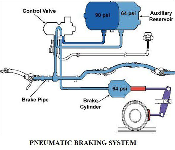
The simplest air brake system consists of an air compressor, a brake valve, series of brake chambers at the wheels, unloader valve, a pressure gauge and a safety valve, and an air reservoir. These are all connected by tubes. Some air braking systems may have additional components such as stop light switch, a low pressure indicator, an air supply valve to supply air for tyre inflation, a quick release air quickly from the front brake chambers when the brake pedal is released, a limiting valve for limiting the maximum pressure in the front brake chambers and a relay valve to help in quick admission and release of air from the rear brake chambers.
Working of pneumatic braking system
The air compressor operated by the engine forces air at a pressure of 9-10 psi, through the water and oil separator to the air reservoir. The air pressure in the reservoir is indicated by a pressure gauge. The reservoir contains enough compressed air for several braking operations. From the reservoir the air is supplied to the brake valve. As long as brake pedal is not depressed, brake valves stop the passage of air to brake chambers and there is no braking effect.
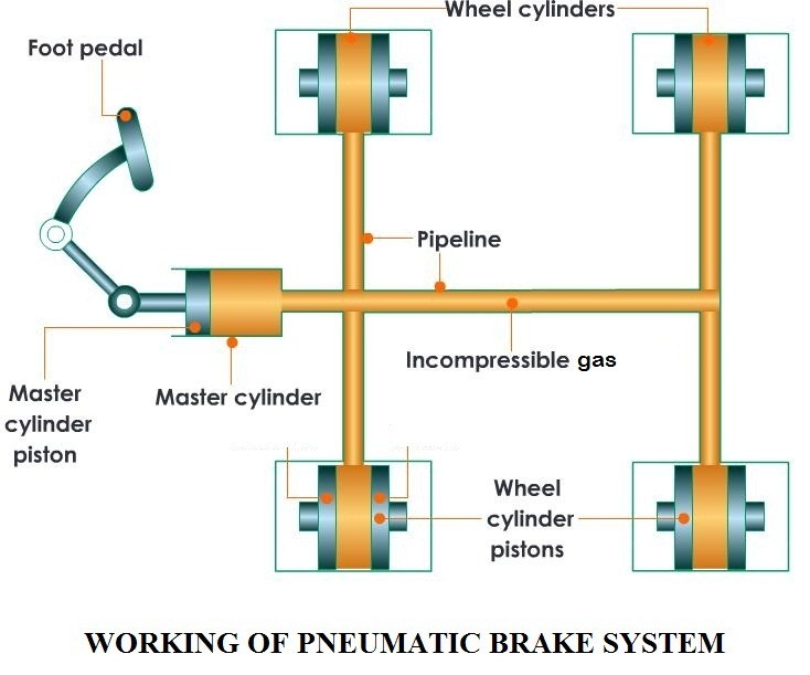
When the brake pedal is depressed, the brake valves varies its position and compressed air is admitted into the wheel brake chambers. In the chambers the air acts upon flexible diaphragms, move4s them the pushes out the rods connected with the levers of the brake gear cams. The cams turn and separate the shoes thus braking the wheels. When the brake pedal is released, the supply of compressed air is cut off from the brake chambers and they are connected to the atmosphere.
The pressure in the chambers drops, the brake shoes are returned to their initial position and the wheels run free.The brake valve is equipped with a servo mechanism which ensures that the braking force on the shoes is proportional to the force applied to the pedal.Besides the valve imparts a relative reaction to the movement of the pedal so that the driver can sense the degree of brake application.
Components of air brake system
Valves
An unloader valve is mounted in the air pressure system between the compressor and reservoir to control the pressure of air in the reservoir. The unloader valve relieves the compressor of its pumping load once the unloader cut out pressure is obtained and seals the reservoir when the compressor has built up a pressure depending upon the setting of the adjusting screw. The unloader then delivers the air delivered by the compressor to the atmosphere thus allowing the compressor to run light whilst the reservoir contains an adequate supply of air.
Air filters
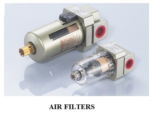
Air filters are used in the air pressure system to prevent particles of foreign matter from entering the operating system airlines or equipment. These are mounted on the chassis and have drain plug to allow the condensate to be easily removed.
Air reservoir
The function of the air reservoir is to store the compressed air so that there will always be an ample supply available for immediate use in brake operation. It provides storage of sufficient compressed air to permit several brake applications even after the engine has stopped and just restarted. It also provides a space where the air is heated during compression might cool, and oil and water vapours condense. An electro pneumatic switch is also incorporated in the circuit. This switch operates in conjunction with the brake valve the stop light, by completing the stop light electrical circuit when brake is applied.
How Pneumatic Braking Systems Work
The Braking Process
- Air Compression: The engine-driven air compressor generates compressed air, typically at pressures between 100-130 psi (pounds per square inch).
- Air Storage: Compressed air is stored in reservoirs, ensuring a constant supply for braking operations.
- Brake Application: When the driver presses the brake pedal, it opens the foot valve, allowing compressed air to flow into the brake chambers.
- Mechanical Action: The air pressure in the brake chambers pushes a diaphragm, which moves a push rod connected to the slack adjuster.
- Brake Engagement: The slack adjuster rotates the S-cam or disc brake caliper, pressing the brake shoes or pads against the drum or rotor, creating friction and slowing the vehicle.
- Brake Release: When the driver releases the brake pedal, the foot valve closes, and the air in the brake chambers is exhausted, disengaging the brakes.
Types of Air Brake Systems
- Single Circuit System: Used in older vehicles, this system has a single air line running to all brakes.
- Dual Circuit System: Modern vehicles use this safer design, which separates the front and rear brakes into two independent circuits.
- Anti-Lock Braking System (ABS): An advanced system that prevents wheel lock-up during emergency braking situations.
Advantages of Pneumatic Braking Systems
- High Braking Force: Capable of generating significant stopping power for heavy vehicles.
- Reliability: Less prone to failure compared to hydraulic systems due to the abundance of air.
- Consistent Performance: Maintains braking efficiency over long periods and repeated use.
- Fail-Safe Design: In case of air pressure loss, spring brakes automatically engage to stop the vehicle.
- Easy Maintenance: Components are easily accessible and serviceable.
- Compatibility: Ideal for use with trailer braking systems in combination vehicles.
Maintenance and Safety Considerations
Regular Maintenance Tasks
- Air Compressor: Check and replace the air filter regularly, typically every 25,000-30,000 miles.
- Air Dryer: Inspect and replace the desiccant cartridge as recommended by the manufacturer, usually every 2-3 years.
- Air Tanks: Drain moisture daily to prevent corrosion and freezing.
- Brake Shoes and Drums: Inspect for wear and replace when necessary, typically every 200,000-300,000 miles.
- Air Lines and Fittings: Check for leaks, damage, or loose connections during pre-trip inspections.
- Slack Adjusters: Ensure proper adjustment to maintain optimal brake performance.
Safety Checks
- Air Pressure Build-Up Time: Monitor the time it takes for the system to reach full operating pressure (typically 100-130 psi).
- Air Pressure Loss Rate: Check for excessive air loss when the brakes are applied and released.
- Low Air Warning: Ensure the low air warning system activates at the correct pressure (usually around 60 psi).
- Spring Brake Activation: Verify that the spring brakes engage at the specified air pressure (typically around 20-40 psi).
- Brake Performance: Regularly test the braking system’s effectiveness through road tests and brake meter assessments.
Technological Advancements in Pneumatic Braking Systems
Electronic Braking Systems (EBS)
Electronic Braking Systems integrate electronic controls with pneumatic systems to enhance braking performance and safety. Key features include:
- Faster response times
- More precise brake force distribution
- Integration with stability control systems
- Advanced diagnostics and monitoring capabilities
Regenerative Air Braking
This innovative technology captures and stores compressed air generated during the braking process, reducing the workload on the air compressor and improving overall system efficiency.
Autonomous Emergency Braking (AEB)
While not exclusive to pneumatic systems, AEB technology is being integrated into air brake systems to provide automatic braking in emergency situations, significantly enhancing vehicle safety.
Conclusion
Pneumatic braking systems are essential for the safe operation of heavy vehicles, offering reliable and powerful braking performance. As technology continues to advance, these systems are becoming more efficient, safer, and easier to maintain. Understanding the principles, components, and maintenance requirements of air brake systems is crucial for drivers, mechanics, and fleet managers to ensure the safe operation of heavy vehicles on our roads.
By staying informed about the latest developments in pneumatic braking technology and adhering to proper maintenance practices, we can continue to improve road safety for all users.
