An Introduction to Taper Turning Methods in Lathe Machines
A lathe machine performs taper turning, gradually reducing the diameter of one portion of a cylindrical workpiece as it machines into another portion. Tapers can be external or internal. If if confines the workpiece to the outside, the taper is external; if it confines the workpiece to the inside, the taper is internal.
In conventional straight turning, the cutting tool travels along a line parallel to the axis of the workpiece, resulting in a completed product that has the same diameter throughout. When cutting a taper, on the other hand, the tool travels at an angle to the axis of the work, resulting in the production of a taper.
Determining the technique used to turn a taper depends on factors such as the taper’s degree, length, placement (whether internal or external tapers on a turret lathe or lathe machine), and the number of pieces to turn.
What is a taper?
A consistent rise or decrease in the diameter of a cylindrical workpiece measures the length for a taper.
- Tapers are classified as inch tapers or metric tapers based on their measuring units.
- Metric tapers are measured in millimeters per meter of length; for example, a 1:20 taper has a 1-mm diameter change in 20mm of length.
What is Taper turning?
Taper turning on a lathe is the process of progressively expanding or lowering the diameter of a cylindrical workpiece to achieve a conical surface.
How taper turning operation can be done on a lathe machine?
The engine lathe, often known as the mother of all machines, is a versatile machine that can do up to 10 distinct machining operations with ease. It’s no surprise that it’s progressed at an exponential rate, and we now have sophisticated CNC turning centers capable of extremely high precision and accuracy in turning. However, when it comes to the lathe machine itself, there are millions of them in use throughout the world, and there is still room for development because it is still one of the most cost-effective pieces of equipment in any machine shop.
Taper turning is one of the procedures conducted on a lathe, and there are numerous strategies for doing so, even with CNC turning machines, and taper turning has its own set of problems. Once it is integrated into any turning lathe, lathe makers and turners utilizing traditional turning machines will enjoy how simple it is to use.
Types of Tapers
- There are two sorts of tapers, according to the American Standard Association. Self-Holding Tapers and Self-Releasing Tapers are two types of tapers.
- Self-Holding Tapers: These are the taper angles that, when correctly placed, stay in place due to the wedging effect of the small taper angle.
- Self-releasing Tapers: People mostly utilize these kinds of tapers for alignment. Steep tapers are another name for them.
Examining Tapers
The following procedures are commonly used to inspect taper:
- Using a simple micrometer
- Using a Taper Micrometer
- Using a Sine Bar
- By chalking lines
Taper Turning Methods
There are five different types of taper turning methods in lathe machines.
1. Form tool method
2. Tailstock set over method
3. Compound rest method
4. Taper turning attachment method
5. Combining feeds method
When using any of these techniques, it is critical that the cutting tool be precisely centered with respect to the axis of the workpiece; otherwise, the workpiece will not be properly conical, and the rate of taper will fluctuate with each cut.
Form tool method, A Taper Turning Operation
Form turning is one of the simplest taper turning processes on a lathe machine to produce a short taper. The below taper diagram shows this method at the required angle. It grounds the form. The tool is fed perpendicular to the lathe axis when the workpiece rotates.

The tool’s cutting edge length must be greater than the taper length. Since the entire cutting edge removes the metal, it will produce a lot of vibration and hence a large force is required. It is done at a slow speed.
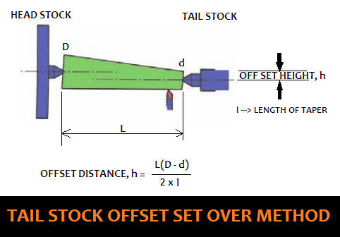
Tailstock set over method
Generally, when the angle of the taper is very small, this taper turning methods in a lathe machine will be employed. The worker places the workpiece in the live center. By turning the set-over method, they move the tailstock in a crosswise direction. This method is known as the “tailstock set over method.”

When it comes to the offsetting of the tailstock in the lathe machine, one thing to consider is the length of the taper. When it comes to the taper, length is important. If the length of the taper varies, the offset will vary as well.
A formula to calculate the tailstock set-over method To calculate the offset height


Hence, here the job is inclined at the required angle. When the workpiece rotates, the tool is moved parallel to the lathe axis so that the taper will be generated on the workpiece.
Advantages of tailstock set over method
- It is possible to offer a power feed.
- It is possible to get a nice surface finish.
- The taper can be made to the maximum length possible.
- Threads on the taper section of the taper can be made externally.
- It is possible to make duplicate tapers.
Disadvantages of the tailstock set over method
- Only the external taper may be turned.
- It’s tricky to get the offset just right.
- When work is held exclusively between the centers, taper turning is achievable.
- The alignment of the lathe centers will be altered (steep tapers cannot be turned), resulting in damage to the work’s center drilled holes.
Compound rest method
Tapering using a swivel compound slide will be the second most straightforward method of creating a taper after that. You can only use it on short tapers. On the compound slide, the designer has chosen an angle that is half of what’s needed for the taper to be included. It is necessary to use caution in order to prevent a bad ending.
A short and steep taper generally produces using these taper turning methods on a lathe machine. To do this, the workpiece is held in the chuck and rotated about the lathe axis. Then, the compound rest swivels to the required angle and clamps in position.

Then, by using the compound rest handwheel, the tool will be fed. This method allows you to turn both internal and external tapers on a turret lathe. A key feature is the ability to swivel the compound rest up to 45° on both sides. You can move the tool by hand.
Why should we use compound rest method for tapering?
This technique provides very accurate results, but it has certain limitations due to the absence of an automated feed and the limited length of the taper. To adjust the compound rest base to the necessary angle for taper turning, it is possible to adjust the compound rest base to the necessary angle for taper turning.
To perform the operation, we need to know the included angle of the taper that will be machined. We can calculate this angle by measuring the angle formed between the two crossing straight lines. The angle formed between the taper and the centerline is one-half of the included angle, and we will adjust the swivel compound rest for this angle when we assemble it.
In the case of a lathe center with an included angle of 60 degrees, we will place the swivel compound rest at a distance of 30 degrees from parallel to the centerline.
Advantages of compound slide:
- Internal and external taper are both possible.
- It is possible to create a steep taper.
- The compound slide is simple to set up.
Disadvantages of compound slide:
- Only hand-feeding is possible.
- The taper section of the threads cannot be manufactured.
- The length of the taper is governed by the top slide’s movement.
Taper turning attachment method
A taper turning attachment uses for longer tapers if the tapers are longer in length. In these taper turning methods, they use a different attachment of the lathe machine by utilizing a bottom plate or bracket. They attach a taper turning attachment to the rear end of the bed. It has a guide bar, which is usually pivotal at its center. The guide bar can swing, allowing them to set it at any required angle. It has graduation degrees.
On either side, the guide bar can be swiveled to a maximum angle of 10°. It has a guide block that connects to the rear end of the cross slide and it moves on the guide bar. Remove the binder screw, before connecting the cross slide, so that you can make the cross slide free from the cross slide screw.

Usually, during taper turning, the job will be held in the chucks or in the centers. At the required angle, the guide bar turned.
The Taper Turning Formula
The angle is calculated using the formula, tan (α/2) = (D-d)/2l or tan θ = (D-d)/2l
The engineer divides the workpiece into millimeters instead of degrees, which yields the angular distance for tilting the guide bar.
The compound rest handwheel indicates the depth of cut. At a half taper angle, the operator sets the guide. By employing these taper turning techniques on a lathe machine, any taper turning task can be accomplished.


Advantages of taper turning attachment:
- Tapers can be made both externally and internally.
- Threads can be cut on both the exterior and interior taper parts.
- It is possible to provide a powerful feed (a long taper can be made).
- A good surface finish may be achieved.
- The lathe center’s alignment is not messed up.
- Because the duration of the work does not affect the taper, it is ideal for making duplicate tapers.
- The work might be done in the chuck or between the centers.
The disadvantage of taper turning attachment:
- Taper angles may only be changed to a certain extent of taper turning.
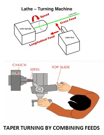
Combining feeds Method
Another more advanced taper turning methodology is taper turning in lathes by combining feeds. Both longitudinal and cross feeds may be engaged concurrently in some lathes, allowing the tool to travel a diagonal course that is the product of the magnitude of the two feeds. The trajectory of the resultant can be adjusted by changing the feed rate by changing the gears given within the apron.
What is a taper in machining?
It is possible to secure the tool bit into the spindle of a machine tool using a machine taper, which is a fastening mechanism that leverages the laws of friction to do so. Milling a tapered profile into the shank or shaft of the tool bit accomplishes this. The tool bit fits into a symmetrical cavity in the spindle of the machine tool to achieve the desired result.
How does a machine taper work?
Workpiece pressure forces the machine to taper into place, and friction over the whole region of contact keeps the bit in place firmly. Tool bits meant for low duty applications often depend just on friction to hold them in place, but those used in high torque machining may additionally be equipped with a key system or be threaded to further secure them. There are numerous different varieties of machine taper in common use, all of which operate on the same fundamental principles and provide a rapid, easy, and cost-effective way of tool bit locking that is simple and quick to install.
How to choose a machine spindle?
Tool bits intended for use in drill presses, milling machines, and lathes need a secure locking mechanism while in use to prevent accidental removal. Operational bits, when subjected to significant stress, can lead to destruction of a workpiece, damage to a machine, or severe harm to the machine operator if not properly secured.
It is possible to produce this locking action with machine tapers by mating a taper-machined shank to a matching groove in the spindle. The friction formed between these two surfaces results in a remarkably secure connection that is capable of sending a significant amount of torque to the tool’s cutting edge. The architecture’s simplicity allows for quick bit changes, resulting in increased productivity overall.
Taper designs for light machine usage, such as drill presses, depend on the friction caused by the taper alone to keep the bit locked in place, according to the manufacturer. Machine tapers for heavy load applications may additionally have a thread cut into the two surfaces or a drawbar system to aid in better seating of the machine taper. Several heavy machine taper designs have a critical element that also contributes to their ability to withstand the high torque forces required. In many cases, machine operators include matching grooves in both tapered tool bits and spindles. They do this to enable a wedge to secure the seat and remove the tool bit.
How many types of taper are there?
Machine Tapers are available in a variety of designs.
Each of the three types of machine taper has its own classification.
1. In accordance with the Class
2. In accordance with Use
3. In accordance with the size
In accordance with the Class
There are two varieties of machine taper, which are distinguished by their class.
1. Self-Holding Taper
2. Quick Release Taper
Self-Holding Taper
It is important to keep the taper angle smaller than 3° when using this form of taper. In this case, the taper is sufficient to keep the assembled component in place without the need for any additional locking mechanism. It is sometimes referred to as a slow taper.
What is the operation of self-locking tapers?
The cone’s included angle is small in a self-locking holder because of the design. When a tool is put into the spindle nose, friction and other forces are sufficient to keep the tool in place and to transfer the forces and torques. These devices are often referred to as shallow-taper holders.
Quick Release Taper
They maintain the taper angle at or above 18 degrees in this type of taper. High Taper Angles require a locking mechanism for proper clamping. They have a taper ratio of 7:24, which is excellent.
In accordance with Use
There are two varieties of machine taper, each with a different use.
1. Internal Taper
2. External Taper
Internal Taper
When the taper is applied to the inner surfaces of a cylindrical job or workpiece, it is referred to as an internal taper.
External Taper
A device that tapers externally on a cylindrical job or workpiece is called an External Taper.
In accordance with the size
There are many different types of taper based on their size.
1. Morse Taper
2. Metric Taper
3. Jarno Taper
4. Brown and Sharpe Taper
5. Standard Pin Taper
6. Jacobs Taper
Which taper is the most often seen in the industry?
Morse Taper
MT 0 to MT 7 Morse Taper is a self-holding type taper that is available in an eight-size range from MT 0. The taper ratio of morse taper is discovered to be 1:10, and its included angle is accessible in three different sizes: 3°, 5/8 inch/foot, and 5/8 inch/foot. Morse taper is mostly utilized in lathe machine drill nose spindle, drill shank, arbor, and other similar applications.
Metric Taper
The metric taper is a self-holding and quick-releasing type of taper that is available in seven different sizes in self-holding and four different sizes in quick-releasing versions. Where MT O to MT 6 sizes are available in self-holding types, while 30°, 40°, 45°, and 50° taper angles are available in quick-releasing types. Metric taper is mostly employed in the nose spindle surfaces of lathe machines.
Jarno Taper
Jarno taper is also a self-holding form of taper that is available in 20 sizes ranging from 01 to 20 sizes in length. These Jarno taper has a taper ratio of 1:20, and it offers an included angle of 0.6 inches per foot of length. Die marking machines mostly utilize this taper, as previously stated.
Brown and Sharpe Taper
In terms of size, the Brown and Sharpe taper is available in both self-holding and quick-releasing versions, with 18 sizes available in self-holding and 09 sizes available in quick-releasing. BS 1 to BS 18 sizes are available in self-holding types, while sizes 4 to 12 are available in quick-releasing types. In the case of the Jarno Taper, the taper ratio is 1:20, and the included angle of the BS 10 is 0.5161 inches per foot.
In addition, all other forms of tapers, including angle tapers, are 1/2 inch per foot. The spindle and arbor of a milling machine are both made of Brown and Sharpe taper.
Pin Taper
A self-holding pin taper is a form of pin taper that is often used. The taper ratio of a conventional pin taper is 1:50 in metrics and 1:48 in British units of measurement. It has a 1/4 inch/foot angle included. Pin taper standard, as used in clamp devices, tapered pin, and so on.
Jacobs Taper:
Jacobs taper is primarily utilized in drill press chucks, arbors, and other similar applications.
Is the Jacobs taper the same as the Morse taper, or are they different?
In the drilling industry, Jacobs Tapers are virtually solely utilized for Drill Chuck Mounting. A broad range of tooling incorporates Morse Tapers, including drill bits, reamers, end mill holders, drill chuck arbors, collet centers and lathe centers, among other things. Brown and Sharpe tapers may be found on comparable tooling, however they are more often seen on older tools and machines than on newer ones.
Taper turning applications
- Tapers are used in manufacturing to make cutting tools such as drill shanks, sockets, and sleeves that can find, retain, and transmit rotational motion from a machine spindle.
- The machine spindle, which is used to drive spinning cutting tools such as drills and reamers, is equipped with a tapered hole that is connected to and driven by the motor shaft.
- The arbor with the taper is driven by the milling machine’s spindle. The milling cutters were held in place by the arbor.
- Assembly of components such as press tools, jigs, and fixtures that are positioned by cylindrical taper pins.
Tapers, also known as self-holding tapers, have a maximum taper angle of 10 degrees. Quick-release tapers feature tapered ends with steeper taper angles, which necessitate the use of extra locking mechanisms on an assembly.
The Tapers are ideal for self-aligning and locating, and they’re used extensively in the assembly of static and dynamic components in engineering.
FAQs
What is the meaning of taper turning?
A turning technique, taper turning has the cutting tool traveling at an angle to the workpiece’s axis, creating a tapered form in the workpiece as the tool moves. As the workpiece turns, its diameter varies evenly from one end to the other, resulting in a tapered piece. You can taper the workpiece from either its interior or exterior.
What operation is the gradual reduction in diameter from one part of a cylindrical workpiece to another part?
The Taper turning is a lathe machining technique that involves gradually decreasing the diameter of a cylindrical workpiece from one end to the other. External or internal tapers are available.
What are the different types of tapers?
Taper is defined as a consistent variation in diameter that results in a wedge or conical shape. The three most popular techniques for taper turning on the lathe are the offset tailstock set-over method, the compound rest method, and the taper attachment method.
The function of the taper turning process is to ____
1. Reduce the diameter of a workpiece along its length
2. Reduce the diameter by removing material about an axis offset from the axis of the workpiece.
3. Remove the material from the end surface of a workpiece.
4. All of the above
Answer:
All of the above
What are the limitations of the form tool taper turning method?
It is limited to cutting short tapers and requires knowledge of either the included angle or center-line angle.
Which of the following is not the method of taper turning?
1. Guide Block
2. Sliding Block
3. Guide Bar
4. Carrier
Answer:
Carrier
Which of the following methods does not involve taper turning?
All of the five methods are examples of taper turning techniques. The user can use the compound rest and the taper attachment techniques with a lathe to turn both internal and external tapers. Meanwhile, they can only use the tailstock offset method to turn exterior tapers.
What is the meaning of tailstock set over?
It is common practice to use a taper turning operation on a lathe machine when the angle of the taper is very small. It is necessary to put the workpiece in the live center. By rotating the set over technique, the tailstock will be moved in a transverse direction, which is perpendicular to the lathe axis, at this point.
Example Problem:
Calculate the tail-stock set over for turning a taper on a job such that its two diameters are 80 mm and 50 mm. The total length of the job is 300 mm, and the length of the tapered portion is 200 mm only.
Solution:
Another formula to calculate offset distance is h = (L (D-d))/2*l)
= (300 (80-50)) / (2*200) = 22.5 mm
What is the best way to specify a taper?
The diameter of the workpiece defines the taper throughout its length. The ratio of the difference in the diameters of the taper to the length of the taper determines the amount of taper, which is known as such. Examples of taper diameters are 1:4, or 0.5:4, etc.
What is the meaning of “taper” in drawing?
A draft of a foundry pattern, as provided by the foundry.
The tailstock set over method of taper turning is preferred for
- Internal tapers
- Small tapers
- Long slender tapers
- Steep tapers
Answer: Option C
Solution
The tailstock set-over method shifts the tailstock from its central position to one side of the bed, tilting the workpiece relative to the lathe axis and feed. This method allows taper turning on a lathe, resulting in the tool cutting the workpiece at an angle to its axis and creating a taper. Long, slender tapers are most effectively turned using the tailstock set-over procedure.
What is the taper turning formula and how does it work?
The set over length may be calculated using the following formula: S=L*(D-d)/2l, where l denotes the taper length, L is the total job length, d denotes the smaller diameter, and D denotes the bigger diameter.
Which technique is utilized only for an internal taper? For turning internal tapers, the suitable method is ____________.
1. Tailstock offset
2. Taper attachment
3. Form tool
4. Compound rest
Answer
Swiveling the compound rest in the lathe allows you to turn the taper. This technique is exclusively used for turning internal tapers, not for turning external tapers. A half-cone angle () is used in this technique to swivel the compound rest, which means that it is rotated in a horizontal plane by half of the conical angle.
An internal or external taper on a turret lathe can be turned by
1. Face turning attachment
2. Taper turning attachment
3. Sliding attachment
4. Morse taper attachment
5. Offsetting tailstock
Answer
Taper Turning Attachment
What is the formula for converting taper to degrees?
Divide the decimal inch by 12 to get the decimal foot taper per foot by dividing the decimal inch by 12. For example, 1.2/12 = 0.1 is a fraction. By calculating the arc tangent of the taper, you may convert the decimal foot taper to a degree angle in degrees. On calculators, the arc tangent is sometimes denoted by the symbols atan or tan-1.
The Formula for the Taper Calculator T = (dl-ds)/L.
Angle of taper in degrees = atan (0.5 x T)
A diameter that is larger (dl), a diameter that is smaller (ds), and the length of a workpiece (L).
What is the best way to test a taper?
An instrument for measuring taper is a taper ring gauge, which is employed.
Describe the method of generation of a long and small taper in a center lathe?
1. Form tool method; 2. Tailstock set over method; 3. Compound rest in a lathe; and 4. Taper turning attachment methods are the four popular methods of generation to produce long and small taper turnings in a center lathe.
In a lathe, taper turning means producing a cylindrical surface by gradually decreasing the diameter of the workpiece.
a) conical surface
b) flat surface
c) both conical and flat surface
d) none of the mentioned
Answer:
Conical surface
What are the operations performed on the lathe other than turning? What are the types of Turning Operations?
Besides turning, a lathe may do the following machining operations:
Lathe Machine types of operations:
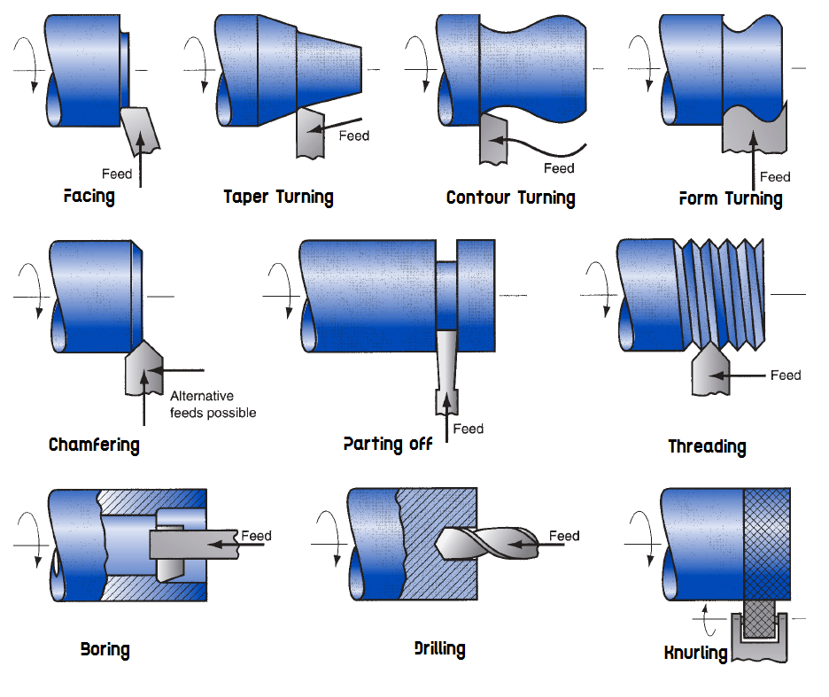
Facing – Feeding the tool radially into the rotational piece to produce a level surface. The machining process, cutting edge shape, tool orientation, and workpiece geometry (either hollow or solid) determine the facing tool’s movement direction. You machine from the outside to the center when roughing and from the inside to the outside when finishing.
Taper turning – It is a cylindrical turning method in which the resultant diameter changes continuously. Conical shafts are made this way.
Contouring – It is possible to contour the turned section by using contour turning instead of turning.
Form turning – It imparts a shape to the work by stabbing the tool radially into it.
Chamfering – The tool’s cutting edge is used to carve an angle into the cylinder’s corner.
Parting off – The tool is radially fed into the rotational work to cut off the end of the component. This action is called parting.
Threading: A pointed tool is fed at a high effective feed rate over the outer surface of the spinning work part, forming threads in the cylinder. The lead screw and feed gear system generate the precise feed necessary for thread cutting. This is done by connecting the main spindle to the feed drive motor.
Boring — A single-point tool is fed along the inner diameter of an existing hole in the component.
Drilling – Drilling on a lathe requires inserting the drill into the rotational work along its axis. Reaming is similar.
Knurling – It is not machining since no material is cut. A regular crosshatched pattern is created by forging metal.


May useful for everyone who were in Mechanical Engineering field
seriously i have gotten what i expect .
you are excellent
Please include Offset distance calculation in your illustration
Great article,thank you very much for sharing this awesome post with us.
Well said and well done.
very informative blog
digital marketing courses in delhi!
Esporti Impex is the best Blood bank refrigerator for blood storage manufacturers in India that also provide a wide range of medical equipment all under one roof, Esporti Impex also is the leading Dressing drum sterilizer manufacturers & supplier in India that provide Dressing drum sterilizer at very competitive prices. blood bank storage refrigerator
Thanks for sharing such a nice blog with full information, we are looking forward to see more blogs in future. We at Kartar Valves understand the expectations of our customers and are continuously meeting the challenge of making three essentials available to our customer viz: Best Quality, Right Price & Timely Deliveries. Cast Iron Ball Valve Manufacturers
Looking for Best Termites services
Pest Control Service for termite in lucknow
ALL TERMITES ARE AND RAISE THEIR YOUNG AS AGROUP.TERMITES EAT NON-STOP, 24 HOURS A DAY, SEVEN DAYS A WEEK!TERMITES ARE OFTEN CALLED THE “SILENT DESTROYER” BECAUSE THEY MAY BE SECRETLY HIDING AND THRIVING IN HOME OR YARD WITHOUT ANY IMMEDIATE SIGNS OF DAMAGE.But not to worry because Bayar pest control is specialize in a wide range of treatment options and have a solution for all common household pests. It is involved in sewage and refuse disposal, sanitation and similar activities.Just visit to our site to get pest control service by clicking on the keyword which is given above in this post.
A comprehensive overview of the various techniques used to achieve tapered shapes in metal turning processes. It covers methods such as offset tailstock method, taper turning attachment, and compound rest method. The content is informative, well-explained, and serves as a helpful resource for individuals seeking to understand and apply taper turning techniques in lathe machine operations.
best steelmans Broaches Company:- Steelmans Broaches Pvt. Ltd. is a renowned Company, which is actively manufacturing push and pull types Straight and Involute Spline Broaches, Surface Broaches, Keyway Broaches, Standard Broaches, Special Profile https://www.steelmansbroaches.com/
Steelmans Broaches Pvt. Ltd. is a renowned Company, which is actively manufacturing push and pull types Straight and Involute Spline Broaches, Surface Broaches, Keyway Broaches, Standard Broaches, Special Profile
https://www.steelmans.com
Great Thank you..
Welcome to Health at Homes: Your Trusted Partner for Foley Catheters at home in Hyderabad. If you or your loved ones require Foley catheter care without the inconvenience of visiting a medical facility, Health at Homes is here to provide exemplary urinary catheterization services directly to your doorstep in Hyderabad.
Metscope is a leading supplier of Color Coated Steel Roofing Sheets, Aluminium Roofing Sheets, Asphalt Shingle Roofing, PUF Sheet, Fiber Cement Board, Purlin, Deck Sheet, Thermal Insulation Sheet, Polycarbonate sheet, Roof Ventilators, Accessories.